XC9536 Small Board

Posted: 2nd August 2013 by riemann81 in CPLD Xilinx
Tags: , , , ,

I have built a small test board expecting to a more complete system, this board was built on single-sided copper layer using the method of photoetching, where most of the components are SMT (Surface Mount Technology).

The CPLD is a Xilinx xc9536 vq44, bought for a few euro on ebay, which i support via a JTAG interface using the Xilinx ISE tool with a programmer for parallel port. The hardware description language that i use widely is Verilog, one of the two most used with the well-known VHDL.

The card mount just 4 diodes LEDs, an expansion port, a JTAG port, 2 buttons and a reset button. The clock comes from the outside through the third pin of the expansion port, to minimize clutter also because the whole thing was built and assembled very quickly just for testing cross compatibility of HW / SW around the ISE toolchain-> Programmer -> CPLD. The clock in this case is generated by a PIC16F628 mounted on a breadboard, very simple, not crucial to describe it in detail.

Coming soon i will post full details of the experimentation board, also based on the same CPLD, but with onboard clock generation using a crystal of 4 MHz, a serial EEPROM, 8 LEDs, 4 buttons plus 1 reset, 2 seven-segment display and a small external expansion port.

Here are some pictures and a video where i show the xc9536 running a program for 4-bit binary count displayed on available 4 LEDs, occasionally interrupted by a manual reset to test the proper operation of the software and hardware.

Read the rest of this entry »

Hello everyone,

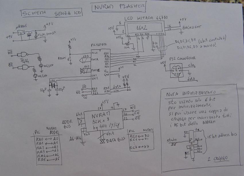
expecting to build a Z80 system, i have constructed this simple programmer for my nvram. I apologize for the circuit diagram drawn by hand, some parts may be hard to read, but it is very simple and intuitive.
The operation consists of inserting data one byte at a time, in hexadecimal, from the keyboard connected via PS2 port, the program steps sequentially and at the next (switched from zero). Once you have finished entering all the bytes you want, by pressing the escape button, the programmer enters reading-mode from location 0 and then hitting Enter you should see the following addresses sequentially and the data they contain.
The board also features a port for debugging and program the PIC via ICD using mikroC PRO for PIC.
Here come some pictures and sources (the project) for that compiler, if you want you can adapt to other software, another pic, etc. … you can modify to your liking, everything is still under development, although it works, but i would also include the possibility of random access to data and also the expansion for the selection of addresses using 2 CMOS CD4040 counters.

Schematic (click to zoom):

Pictures and sources (click to zoom). Read the rest of this entry »

Hi, these days I did some testing for the management, through the USB protocol, of a stream of data to a PIC18F2550, using an HID class device firmware and VisualC # as a language for the application on Windows, and i wanted to publish my work (more than a week working on).

We start from the hardware configuration that i made on breadboard, it is standard pattern for this type of applications, which can be expanded at will of the designer (the pattern is a classic pattern taken from the web, nothing innovative):

Read the rest of this entry »

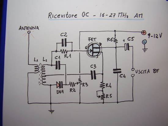
AM Receiver with a FET

This project was created with the aim of creating a very simple receiver to hear the AM modulation of the CB in my town. It is not a recent creation, is a couple of years old , but recently i picked up from the drawer of the “memories”.

Read the rest of this entry »