Hi, these days I did some testing for the management, through the USB protocol, of a stream of data to a PIC18F2550, using an HID class device firmware and VisualC # as a language for the application on Windows, and i wanted to publish my work (more than a week working on).
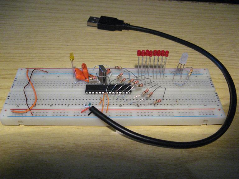
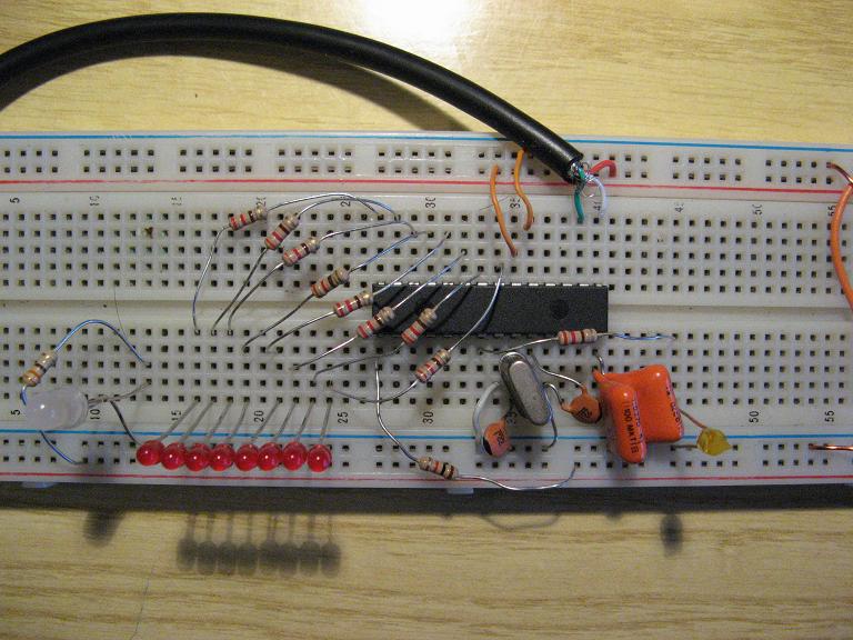
We start from the hardware configuration that i made on breadboard, it is standard pattern for this type of applications, which can be expanded at will of the designer (the pattern is a classic pattern taken from the web, nothing innovative):

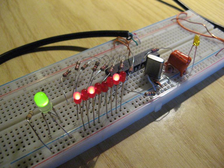
I have attached a series of 8 LEDs with 220 Ohm resistors on PORTB and LEDs on the port that flashes when the USB is recognized by Windows. The firmware that i did, as HID class, can be modified at will to determine how big the buffer must be read and write via USB, and to give a unique identification code so that it is not confused with other USB devices connected to the PC, this code is given by the pair VID and PID (Vendor ID and Product ID), which in my case i chose 1234 and 0001 (in hex). Written and compiled the HID descriptor, coupled to the main(), or what determines what to do when they get data from USB, you have to program the PIC18F2550. Hex is available in the source that i provides.
The first time you connect the hardware inside the FW just mentioned, Windows will install automatically HID (Human Interface Device) which can be seen between devices (resource management), assigned with your own VID and PID.
We now have the hardware connected and recognized, not just open the door of communication via the USB HID class with a programming language of your choice, i typically use the C or Basic, essentially, but because i want a nice view interface i use VisualC # (via the programming of Windows Forms).
The program i wrote is very simply: you connect the device with VID and PID 1234 and 0001, and once connected you can send a byte to the PIC via USB typing data in a box, in decimal, and pressing SEND.
This is the first step to communicate from one application to win out on a device interfaced to the USB, everything has been written by hand, FW and SW, and so we have full control (or almost) of everything happens and what can not work.
Here is an issue on which i spend some time, but not much yet.
To properly write the firmware (written in C) on the PIC, through any programmer, you must properly configure the configuration bits of the microcontroller. The PIC that i have chosen have this internal structure block (as you note is a page of datasheet from Microchip ®, please read it for more detail):

We need to set the behavior of the multiplexer according to our oscillator, i chosen a crystal of 4 MHz, then the correct settings (found after several trials) are these:
- 96 MHz PLL prescaler : No Divide (4 MHz input)
- CPU System Clock Postscaler: [OSC1/OSC2 Src: /1][96MHz PLL Src: /2]
- Full-Speed USB Clock Source Selection: Clock src from OSC1/OSC2
- Oscillator: XT: USB-XT
It ‘s very important to use XT oscillator and NOT HS if we use a crystal, and also that the USB works at 48 MHz, as we are doing now, in fact signed by the multiplexer with selection USBDIV is coming out exactly a frequency of 48 MHz, half of that generated by the internal PLL.
If these paths are not set up correctly with the internal configuration bit, windows does not recognize anything, placing doubts over the entire system, will the FW I’ve written correct? HW will be wrong some connection? … probably not been set correctly these configuration bits.
Last thing very important and quite critical, due to many failures, is the capacitor on VUSB of 220nF, the value is not critical, but criticism is its lack.
Now let’s see some pictures of HW and then a video of the operation:

I’ll give you the source of the firmware, also you will find the . hex ready for those wishing to try
Here are the sources in VisualC # application that communicates with the device, will find the sources and also the little program already compiled in executable format:
If you want you can try to read some source, modify it, recompile it for other PICs, for example, 18F4550, and if you try even if the exe will run properly with your HW / FW, use other ports of the PIC, have them do other things (instead to view the status with the 8 LEDs), everything is editable and customizable.
As you may have noticed i have not made a pcb as this trial is not definitive but is a pattern seen more as a “testbench” for various uses, attempts to work at an hardware and software interfaced to the USB device under the operating system Microsoft Windows.
All the real work was to understand how the bytes are sent via USB from a Windows application to a digital port of a MCU, so most of the time was used to fully understand how to write the HID firmware and run it with all the real problems encountered as settings, frequency, fuses … etc. ..
I hope it was to your liking.

Pingback: Charlie
Pingback: Kim Kardashian