AM Receiver with a FET
This project was created with the aim of creating a very simple receiver to hear the AM modulation of the CB in my town. It is not a recent creation, is a couple of years old , but recently i picked up from the drawer of the “memories”.

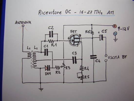
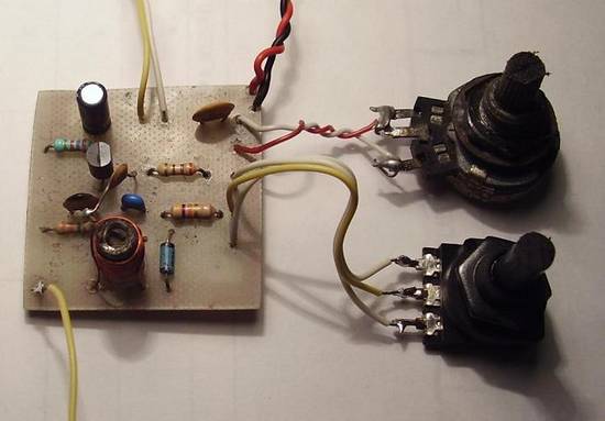
My receiver can, in theory, cover the range between 16 and 30 MHz, using an active FET BF245. This is a classic pattern of reaction receiver, carried out through retroactive part of the signal routed to the gate of the FET through the tuning circuit consisting of L2, C1 and the varicap diode DV1. The amount of reaction, upon which the sensitivity of the system, is determined by potentiometer R5. If you exceed in that regulation of reaction, the receiver will come under the self-oscillation, so you have to training your ear, is a matter of habit in use such of these receivers, which are well attuned to the adjustment of the reaction.
We notice that they are self oscillatory regime when through the headphones you hear a whistle that covers all possible received signals.
The line is controlled by the varicap DV1, and adjusted by varying the voltage applied to it using the potentiometer R3.
The low-frequency output is taken through the electrolytic capacitor C5 (a tantalum would be perfect), after filtering the high frequency components through C4. Of course, as you can see, the level of the output signal is too low to be heard directly in the headphone or speaker, but just any preamplifier with high input impedance and a small glides, TDAxxxx for example, to listen in speaker. For my tests i used the mic input of my stereo system, and the clarity of the signal was discrete, reminding us that the receiver is still very simple.
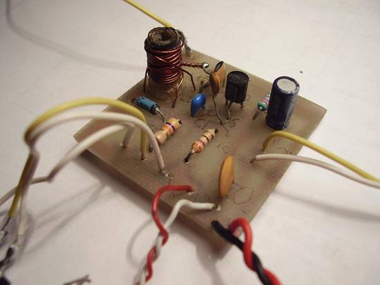
The construction of the coils L1/L2, to wrap up over ferromagnetic core, is a crucial part of the project. In fact the only action on the tuning knob us to vary the bandwidth up to 6-7MHz, not making us cover the entire band from 16 MHz to 30 MHz for this fact is necessary to calibrate the ferromagnetic core, with an anti-inductive screwdriver, so that we can focus our band of interest, if the lower (16 to 23 MHz) or upper (23 – 30 MHz). The coil L2 is formed by 12 turns of enamelled copper wire of 0.5 – 0.6 mm in diameter up to a base with a core of 6 mm in diameter, taking a grip in the fourth coil to ground. The coil L1 is wound with 4 turns of the same wire, on the same media, from the “cold” L2 side, also called ground side.
Connect an antenna to receive signals in OC, possibly adjusted to the wavelength, or a stub, the old gang that has been chosen to receive. For example if I want to receive from 23 – 30MHz, choose a dipole receiver for 26-27 MHz with an appropriate length of wire should also receive something, but I have not personally tried.
When you turn on your receiver, you sling the potentiometer of the reaction, and is always kept on the limit of self-oscillation, this is indeed the point of maximum sensitivity of the receiver, but is also relatively complicated to keep exactly to the limit of self-oscillation. With some practice it will not be hard to use it.


Pingback: Learn Even more Here
Pingback: More methods
Pingback: visit the following web site
Pingback: visit the next web page
Pingback: win at Roulette
Pingback: Greavy Accountants Dublin
Pingback: Best Cars Toronto
Pingback: Lake Forest IL
Pingback: custom photo puzzle
Pingback: chicken recipes
Pingback: gopher
Pingback: Trabalho em casa
Pingback: yummy recipes
Pingback: eat stop results
Pingback: How to get your ex back
Pingback: Boiler Service
Pingback: youtube.com
Pingback: website
Pingback: vegetarian times
Pingback: ของขวัญรับปริญญา
Pingback: Tankless Water Heaters
Pingback: energy medicine in calgary
Pingback: Automated Income App Review
Pingback: youtube.com
Pingback: youtu.be/7lG9F8gCW8U
Pingback: informative post
Pingback: schnell abnehmen tipps
Pingback: look at these guys
Pingback: implant dentists
Pingback: treatment of cellulite
Pingback: vous pouvez essayer ici
Pingback: how to make yourself taller
Pingback: http://youtu.be/OycLaTZQjS0
Pingback: http://www.youtube.com/watch?v=WFGexdjtNOc
Pingback: Buy cosmetics, Buy Carbon products, Buy Books, Buy baby products, Buy Babies & Kids prodcuts, Buy Body Care, Buy Candles, Buy Cleaners, Buy Pets Products
Pingback: Forex Strategy Master, Forex Strategy Master discount, Forex Strategy Master review, Forex Strategy Master bonus
Pingback: mlm
Pingback: Forex Strategy Master, Forex Strategy Master discount, Forex Strategy Master review, Forex Strategy Master bonus
Pingback: more infos
Pingback: Forex Strategy Master, Forex Strategy Master discount, Forex Strategy Master review, Forex Strategy Master bonus
Pingback: http://www.youtube.com/watch?v=djUaNYb4hHM